In this post, I am going to explain “Components of Flink”, “Task Execution”, “Task Chaining”, “Data Transfer”, “Credit-Based Flow Control”, “State Management and State Backend”
You may see the all my notes about Apache Flink with this link
Before starting, because of Flink is implemented in Java and Scale, all components run on JVM.
Components of Flink
- A Flink setup consists of 4 different components:
- JobManager
- ResourceManager
- TaskManager
- Dispatcher
JobManager
- JobManager is the master process that controls the execution of a single application.
- Each application is controlled by a different JobManager.
- JobManager converts the JobGraph into a physical dataflow grap(also called ExecutionGraph) which consists of tasks that can be executed in parallel.
- Once JobManager receives enough TaskManager slots, it distributes the tasks of the ExecutionGraph to the TaskManager that execute them.
- During execution, the JobManager is responsible for all actions that require a central coordination such as coordination of checkpoints.
- JobManager(and also application itself) consist of:
- JobGraph(also called logical dataflow)
- JAR file that contains all the required classes, libraries and other resources
ResourceManager
- It is responsible for managing TaskManager slots.
- When a JobManager requests TaskManager slots, the ResourceManager instructs a TaskManager with idle slots to offer them to the JobManager.
- ResourceManager takes care of terminating idle TaskManagers to free compute resources.
TaskManager
- TaskManagers are the worker processes of Flink.
- Typically there are multiple TaskManagers running in a Flink setup.
- Each TaskManager provides a certain #slots. The #slots limits the #tasks a TaskManager can execute.
- After TaskManager has been started, a TaskManager register its slots to the ResourceManager. When instructed by the ResourceManager, the TaskManager offers one or more of its slots to a JobManager.
- The JobManager can then assign tasks to the slots to execute them.
- During execution, a Task manager exchanges data with other TaskManager that run tasks of the same application.
Dispatcher
- Dispatcher runs across job executions and provides a rest interface to submit applications for executions.
- Once an application is submitted(via web ui, or command line), it starts a JobManager
- The Rest interface enables the dispatcher to serve as an HTTP entry point to clusters.
- The dispatcher also runs a web dashboard to provide information about job executions.
Task Execution
- This is the hard part to explain and understand (at least for me:) )
- Before diving to explain, we should remember to what is operator and task in Flink.
- In general, keep in mind that: Operator = ( Task1+Task2+…TaskN)
- Operator in Flink => transform one data stream to another (this could be the either same type of data stream or different type of data stream). Operators are the nodes of the logical dataflow graph(also called JobGraph)
- Task in Flink => is a basic unit of work executed by Flink’s runtime. Tasks are the nodes of physical dataflow graph(also called Execution Graph).
- Task is one parallel instance of an Operator or Operator chain.( two or more consecutive Operators without any repartitioning in between)
- Each Task has only one thread and there is no sharing knowledge between Tasks in the Apache Flink. For example, Task1 doesn’t know the what is going on another Tasks. This means API provides that each piece of state can be accessed from within one Task. There is no way to access state in other threads.
- And also there is concept of Sub-Task. Sub-Task is a Task that works on the one part of the data stream. SubTask points that there are multiple parallel Tasks for the same Operator or Operator chain. (If you read my previous post, this actually means that there is a data parallelism)
Now, don’t forget the terms Operator, Task and Sub-Task.. Now we can move to the Task Execution part:
- TaskManager(worker/slave process) can execute several tasks at the same time. The concurrent number is usually related to the CPU number of the machine that TaskManager works on it. For example, if your machine’s CPU number is 16, a TaskManager can run 16 tasks at the same time.(This is the best solution that Apahce Flink offers. You can run +16 tasks at the same time, but this could lead some problem — Flink cluster could re-start itself frequently etc — )
- One TaskManager executes its task multi-threaded in the same JVM process
- Tasks can be subtasks of the same operator(remember data parallelism) or a different operator(remember task parallelism) or even from a different application.
- A TaskManager offers a certain number of slots(related to CPU number of the machine) to control the #tasks it is able to concurrently execute.(In other words, if your machine has 16 CPUs, then TaskManager can have 16 slots where each slot processes a task)
Note: Don’t forget that, a slot could contain a specific task or multiple associated tasks
Task Chaining
- This is technique where Flink puts the two subsequent transformations in the same thread, if it is possible. (For example, two subsequent map transformations)
Data Transfer
- The TaskManager take care of shipping data from sending task to a receiving task.
- Each TaskManager has a pool of network buffers to send and receive data.
- If the sender and receiver tasks run in separate TaskManager processes, they communicate via the network stack of the operating system. Sender task serializes the outgoing records into a byte buffer and puts the buffer into a queue. The receiver task takes the buffer from queue and de-serializes the incoming records.
- If they are in the same process, there is no need for network connection.
Note: Each pair of TaskManagers maintain a permanent TCP connection to exchange data.
Credit-Based Flow Control
I have not enough knowledge to go into detail about this topic. Because this topic deals with network stack.
Simply put, this mechanism(credit-based flow) is to fully utilize the bandwidth of network connections especially for problems about back-pressure in TCP.
You may go to the this link to learn about details https://flink.apache.org/2019/06/05/flink-network-stack.html
In this mechanism: - A receiving task grants some credit to a sending task, #network buffers that are reserved to receive its data. - Once a sender receives a credit notification, it ships as many buffers as it was granted.
State Management and State Backend
Let’s remember what is state in Flink.
State can be considered as memory in operators in Flink that remembers information about past inputs. And state can be accessible for task’s business logic.
A task receives input and while task executing its logic, it can read and update its state and also task’s output can be determined by state.
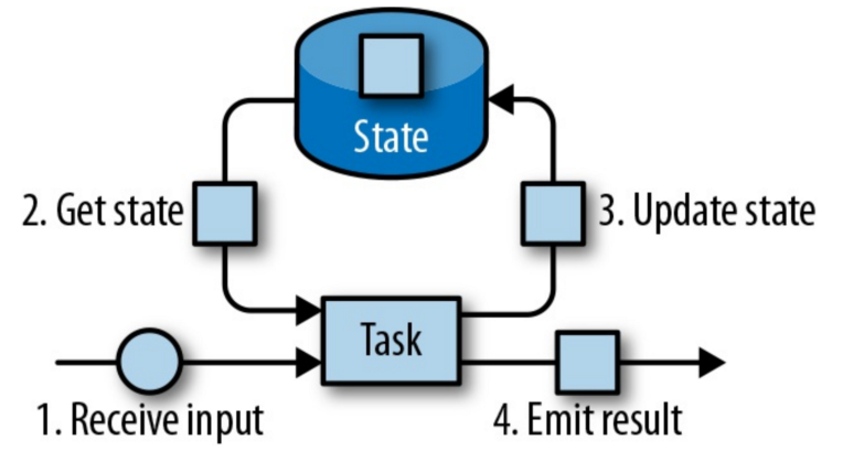
In Flink, State Management is done by according to state type. There are 2 types of state “operator state” and “keyed state”.
State Management — Operator State
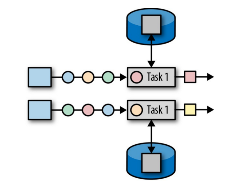
With operator state, one operator instance corresponds to a state. This means that all records processed by the same parallel task have access to the same state.
However don’t think that all parallel tasks use the same state from the same place. In flink, state is always local, each task has its own state, there is no sharing and visibility.
State Management — Keyed State
This state is like a key-map value where specific task will access to the correspond state with its key. In another words, if you have keyed stream with keyed by let’s say color, then stream with blue color will access the blue’s state, stream with red color will access the red’s color state etc …
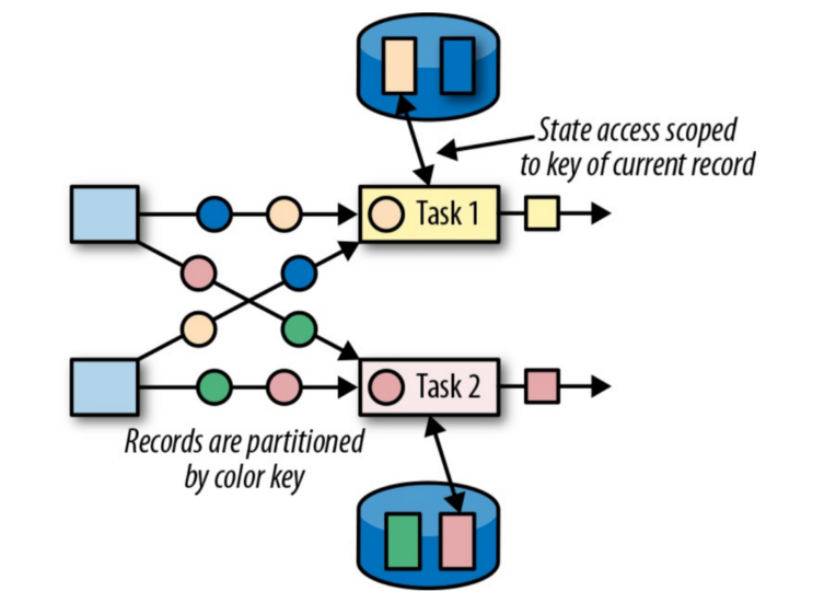
In this example, task 1 receives record with key yellow, therefore task 1 can only access yellow’s state. After that record, if task1 receives record with blue key, task1 will only access the blue’s state.
State Backends
This part should be explained in detail other post. In here, I am just giving abstract view of state backend mechanism.
- A state backend is responsible for 2 things: local state management and checkpointing state to a remote location.
- For local state management, we have 3 options:
- The MemoryStateBackend which holds data internally on the Java heap.
- The FsStateBackend which writes state snapshots into files.
- The RocksDBStateBackend which writes state snapshots into RocksDB database.
- State checkpointing:
- Because of TaskManager may fail at any point in time, its storage must be considered volatile. A state backend takes care of checkpointing the state of a task to a remote and persistent storage. The remote storage for checkpointing could be a distributed filesystem or a database system.
